ABP Scaffolding ABP Scaffolding

5 Tips What Is Sleeve Joint Coupler Tensile Strength?

Time:2026-10-20 Author:Amelia
0%

Understanding sleeve joint coupler performance begins with one practical question: what is the tensile strength of a sleeve joint coupler? The answer is not a universal number. It depends on the coupler design, steel grade, bar diameter, thread quality, installation method, and testing conditions. A coupler may look robust on a workbench, yet perform differently when threads contain dust or the joint is poorly aligned. Small details matter.

This introduction presents five practical tips for evaluating tensile strength with greater confidence. It considers manufacturer data, certified laboratory testing, failure patterns, and relevant engineering standards. Reliable evidence should show the test method, specimen details, loading speed, and recorded failure load. Look for traceable reports. Ask clear questions.

Experience from construction sites also reveals a common weakness: installation records are often incomplete. That gap can make a strong product appear unreliable, or hide a preventable assembly error. Engineers should compare the coupler’s rated capacity with the reinforcing bar’s strength and the project’s design requirements. They should also inspect thread engagement, tightening procedures, and visual damage before testing.

No single brochure proves field performance. Real conditions vary. This guide avoids treating tensile strength as a marketing promise. Instead, it encourages careful verification, qualified technical advice, and honest interpretation of test results. Some conclusions may remain uncertain without project-specific evidence, and that is worth acknowledging. Reliable decisions come from measured data, competent installation, and consistent quality control.
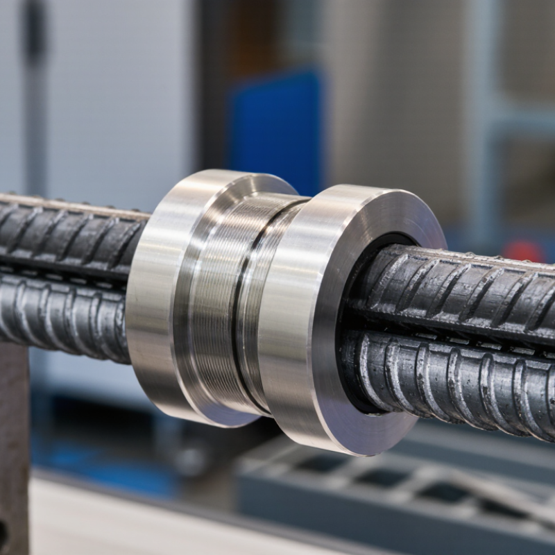
5 Tips What Is Sleeve Joint Coupler Tensile Strength?

What Is the Tensile Strength of a Sleeve Joint Coupler?

What is the tensile strength of a sleeve joint coupler? It is not one universal number. Strength depends on the reinforcing bar grade, sleeve design, thread or grout system, and installation quality. For a 420 MPa yield-strength bar, ACI 318-19 requires a Type 2 mechanical splice to develop the bar’s specified tensile strength. Under ASTM A615 Grade 60 requirements, that value is commonly 550 MPa minimum. Therefore, the coupler should transfer at least 550 MPa without premature failure.

Testing must confirm this performance. ASTM A1034 describes methods for evaluating mechanical splices under tensile loading, including strength, elongation, and failure location. ISO 15835 also addresses mechanical splicing requirements and test procedures for reinforcing steel. A reliable test report should identify bar diameter, steel grade, sleeve type, applied load, displacement, and whether the bar or coupler failed. Numbers without these details are weak evidence.

Installation matters greatly. Misaligned bars, incomplete threading, poor grout filling, or contaminated surfaces can reduce actual capacity. Field inspectors often check thread engagement and verify the installer’s torque or grout records. A simple MPa number can mislead. I would not approve a coupler from tensile data alone. The failure should occur in the bar, not inside the sleeve or at the joint. That distinction is easy to miss, especially when laboratory conditions are cleaner than a crowded construction site.

How Sleeve Joint Couplers Transfer and Resist Tensile Loads

What Is Sleeve Joint Coupler Tensile Strength?

Sleeve joint coupler tensile strength describes how much pulling force a connection can resist before failure. It is not a universal number. The result depends on bar grade, sleeve design, installation quality, and testing conditions. In reinforced concrete work, the coupler joins two bar ends inside a steel sleeve. The connection must transfer tension without allowing harmful slip or sudden fracture.

The load travels through several contact points. Threads, grout, wedges, or mechanical locks grip the bar surface. The sleeve then spreads the force around the joint and carries it toward the opposite bar. Proper engagement is essential. A short thread, uneven tightening, or trapped debris can reduce the effective load path. Small errors matter.

A reliable assessment compares the coupler’s tested capacity with the connected reinforcement’s strength. Engineers also inspect alignment, bar insertion depth, torque, and visible damage. Tensile tests usually measure yield behavior, ultimate load, and permanent elongation. These details reveal more than a single strength value. In practice, no connection is perfectly uniform. That assumption can mislead. Site conditions may differ from laboratory results, especially when workers rush installation or tools lose calibration. A careful quality plan records each joint and checks critical samples before the structure carries design loads.

Which Factors Influence Coupler Tensile Strength?

Sleeve joint coupler tensile strength depends on more than the steel sleeve. It reflects bar grade, thread geometry, sleeve length, grout quality, and installation accuracy. ASTM A706/A706M Grade 60 reinforcement has a specified minimum tensile strength of 80 ksi, or about 550 MPa. A coupler should transfer the bar’s required capacity, not merely carry a convenient test load. ACI 318-19 also distinguishes mechanical splices by their performance under tension.

Tip 1: Check the bar grade before comparing coupler data.

Tip 2: Confirm whether the test uses the same bar diameter and connection type.

Installation often controls the result. Inadequate bar insertion can leave a visible gap inside the sleeve. Poor grout mixing creates weak zones around the bar. Misalignment may introduce bending before direct tension develops. ASTM A1034/A1034M provides test methods for mechanical splices, while ISO 15630-1 describes tensile testing for reinforcing steel. Their procedures improve comparability, but field performance can still differ.

Tip 3: Request full test reports, including failure location, slip, load rate, and sample count.

Tip 4: Inspect insertion depth and grout flow on site.

Corrosion, temperature, repeated loading, and surrounding concrete confinement also deserve attention. A sleeve may reach a high laboratory load yet perform poorly after installation defects or long exposure. That uncomfortable gap matters.

Tip 5: Compare ultimate strength, yield behavior, and measured slip, rather than one headline value. A neat calculation can still mislead when workmanship is assumed perfect.

How to Test and Verify Sleeve Joint Coupler Performance

Sleeve joint coupler tensile strength shows whether a reinforcing-bar connection can carry design loads safely. Testing must follow a controlled, repeatable procedure. ACI 318-19 states that Type 1 mechanical splices should develop at least 1.25 times the bar’s specified yield strength. Type 2 splices must reach the bar’s specified tensile strength. ASTM A1034/A1034M provides mechanical-splice test methods, while ISO 15835 addresses performance and inspection requirements.

Tip 1: Confirm the bar grade and diameter before testing. Tip 2: Inspect threads, sleeves, and insertion marks. Tip 3: Use a calibrated universal testing machine. Record load, displacement, and failure location. The specimen should be aligned carefully. Eccentric loading can create misleading results. It happens easily.

Tip 4: Test several samples, not one. A practical laboratory program often uses three or more specimens for each configuration, following project specifications. Compare the average result with the required tensile strength, but review every failure separately. Tip 5: Check whether failure occurs in the bar, coupler, or threaded interface. A bar fracture outside the sleeve usually indicates effective load transfer. However, one successful test does not prove field reliability. Installation torque, contamination, thread damage, and incomplete bar insertion can change performance. I would also photograph each specimen before and after testing, because small installation details are often missed in written records.

5 Tips: What Is Sleeve Joint Coupler Tensile Strength? — How to Test and Verify Sleeve Joint Coupler Performance

Tip Verification Dimension Technical Basis or Formula Example Calculation or Test Record Acceptance Reference Result / Interpretation
1 Confirm the reinforcing-bar grade and diameter Tensile performance depends on the bar’s specified yield strength, tensile strength, and cross-sectional area. Nominal area is calculated as A = πd²/4. Generic Grade 500 bar, diameter 25 mm:
A = π × 25² / 4 = 490.9 mm²
Use the bar standard and project specification. The coupler must be qualified for the actual bar grade and diameter. Correct bar identification is required before testing.
Measure coupler installation dimensions Record coupler length, outside diameter, bar insertion depth, thread engagement where applicable, and the designed centerline position. Example inspection record:
Coupler length: 100 mm
Outside diameter: 38 mm
Required bar insertion depth: 50 mm per side
Measured insertion depth: 51 mm / 50 mm
Use the approved manufacturer-neutral product drawing and installation procedure. Insertion measurements meet the stated installation requirement.
2 Calculate the required tensile-force benchmark Yield load Py = A × fy. For Grade 500 steel, fy = 500 N/mm² is used in this example. 25 mm bar:
Py = 490.9 × 500 = 245.5 kN
The calculated value is a benchmark only; the governing project code and bar certification control the final requirement. The benchmark provides a transparent basis for comparing coupler capacity with the connected bar.
Check the required strength category ACI 318 distinguishes mechanical splice strength categories. A Type 1 connection develops at least 1.25fy; a Type 2 connection develops the specified tensile strength of the bar. For a 25 mm Grade 500 bar:
Type 1 benchmark = 1.25 × 245.5 = 306.9 kN
If fu = 600 N/mm², bar tensile-force benchmark = 490.9 × 600 = 294.5 kN
Select Type 1 or Type 2 according to the structural design, seismic requirements, and applicable edition of the code. The required category must be stated before the laboratory test begins.
3 Use a controlled tensile-test setup Test the assembled bar–coupler–bar specimen in a calibrated universal testing machine. Align the specimen axially to limit bending and secondary stresses. Recommended recorded items:
Machine capacity: ≥ 500 kN
Load-cell calibration: valid before testing
Specimen alignment: checked and recorded
Test temperature: 23°C
ASTM A1034/A1034M provides test methods for mechanical splices and mechanical connections of reinforcing bars. ISO 15835 provides requirements and test principles for reinforcing-bar mechanical splicing devices. A valid calibration and axial alignment are essential for reliable results.
Record load, displacement, and failure location Capture the load–displacement curve, yield or proof load, maximum tensile load, slip, elongation, and the failure location. Example test-record format:
Maximum load: ≥ 306.9 kN for the Type 1 benchmark
Failure location: bar outside the coupler preferred
Visible coupler fracture: not permitted where prohibited by the project specification
Report actual measured values from the laboratory; do not substitute calculated benchmarks for test results. A complete record allows the connection, bar, and test setup to be assessed separately.
4 Verify slip and deformation behavior Strength alone does not describe service performance. Measure relative movement between the bar and coupler using displacement gauges or an extensometer. Record at minimum:
Initial gauge length: measured before loading
Slip at specified load: measured and reported in mm
Permanent deformation after unloading: reported in mm
Use the slip limit stated in the applicable qualification standard or project specification. Do not assume one universal slip limit for every coupler type. The connection should satisfy both tensile-strength and deformation criteria where required.
Inspect the specimen after testing Visually inspect the coupler, threads, grout or locking components where applicable, bar ribs, and any fracture surfaces. Inspection checklist:
Coupler splitting: none
Thread stripping: none
Bar pullout: none
Unintended bar fracture: documented if present
Failure mode must be compared with the acceptance criteria for the selected connection system. A connection can reach a high load but still require review if excessive slip or an unacceptable failure mode occurs.
5 Use repeat specimens for qualification Test multiple independently assembled specimens because installation quality, bar tolerances, and assembly variation can affect performance. Suggested qualification matrix:
Bar diameters: at least the smallest and largest sizes in the product range
Specimens per condition: as required by the governing standard or project specification
Installation crews: include actual field installation personnel where practical
ISO 15835, ASTM A1034/A1034M, and the project specification may define the number of specimens and loading sequence. A single successful specimen is not sufficient evidence of production consistency.
Prepare a traceable verification report Link each result to the bar heat or batch, coupler lot, installation date, installer, test machine, calibration certificate, and test procedure. Minimum report fields:
Specimen ID, bar diameter and grade, coupler size, assembly measurements, load–displacement data, maximum load, failure mode, photographs, and approval status.
Acceptance status should be stated as Pass, Fail, or Requires Engineering Review against the identified criteria. Traceability makes the test result suitable for quality control and project records.
Technical note: The calculated loads above are engineering benchmarks based on the stated bar diameter and assumed Grade 500 properties. Final acceptance must follow the applicable structural code, reinforcing-bar standard, coupler qualification standard, design drawings, and project specification.

Five Practical Tips for Selecting a Strong Sleeve Joint Coupler

When assessing sleeve joint coupler tensile strength, selection should begin with the connection, not the catalog number. Match the coupler to the reinforcement diameter, steel grade, and joint type. A threaded sleeve needs clean, correctly formed threads. A grouted sleeve needs verified grout strength and complete filling. Small gaps can become serious weaknesses.

Request test reports showing yield strength, ultimate tensile strength, slip, and failure mode. Independent laboratory data is more useful than an unsupported maximum load. Check the coupler’s internal dimensions and gripping length. The sleeve must engage enough steel without damaging the bar. Measure carefully. A few millimeters can matter. Also confirm whether testing reflects repeated loads, static tension, or both.

Consider installation conditions before approving the design. Dust, moisture, poor alignment, and limited workspace can reduce actual performance. Select a system with clear torque, insertion, or grouting requirements. Train installers and inspect sample connections on site. Leave a sensible safety margin above the calculated load. Do not rely on tensile strength alone. A strong sleeve may still fail when installation quality is weak. The fifth check is often skipped: review the supplier’s quality records, traceability, and inspection process. No system is perfect, and field conditions can expose assumptions that looked reasonable on paper.

What Is Sleeve Joint Coupler Tensile Strength?

Tensile strength is the maximum pulling stress a connected rebar-and-coupler assembly can withstand before failure. For a reliable sleeve joint coupler, compare its tested capacity with the specified tensile strength of the connected reinforcement bar.

The chart shows minimum tensile-strength benchmarks for common ASTM A615/A615M reinforcing-steel grades. Values are rounded conversions from ksi to MPa and are reference benchmarks, not product-specific coupler ratings.

1. Match the bar grade
Choose a coupler qualified for the exact rebar grade and diameter.
2. Check the failure requirement
Confirm that the assembly reaches the specified bar tensile-strength requirement.
3. Review test evidence
Request independent tension-test results for the complete joint.
4. Verify installation quality
Follow the required threading, positioning, torque, or filling procedure.
5. Consider site conditions
Account for corrosion, fatigue, temperature, seismic demands, and inspection access.

FAQS

What does sleeve joint coupler tensile testing measure?

It shows whether a reinforcing-bar connection can carry the required design load safely. The test records load, displacement, and failure location.

What strength should a mechanical splice achieve?

Type 1 splices should reach at least 1.25 times the bar’s specified yield strength. Type 2 splices should reach the bar’s specified tensile strength. Check the project requirements too.

Which details must be confirmed before testing?

Confirm the bar grade and diameter before preparing specimens. Inspect threads, sleeves, insertion marks, and visible damage. A small mismatch can distort the result.

How should a tensile test specimen be installed?

Align the specimen carefully inside a calibrated universal testing machine. Record the load and displacement continuously. Eccentric loading can produce misleading results. It happens easily.

How many specimens should be tested?

Test three or more specimens for each connection configuration when project requirements allow. Compare the average result with the required strength. Review every failure separately.

What does the failure location reveal?

A bar fracture outside the sleeve often indicates effective load transfer. Failure may also occur inside the coupler or at the threaded interface. One successful specimen proves very little.

What installation problems can reduce coupler performance?

Incorrect torque, contamination, thread damage, and incomplete bar insertion can weaken the connection. Dust and moisture may also affect installation quality. Small gaps matter.

What should test reports and supplier records include?

Request yield strength, ultimate tensile strength, slip, and failure mode results. Review internal dimensions and gripping length. Also check traceability, quality records, and inspection procedures. I would not rely on a claimed maximum load alone.

How should grouted sleeve connections be assessed?

Verify the grout strength and confirm complete filling around the bar. Unfilled spaces can become serious weaknesses. Repeated-load performance may require separate testing.

Why is field inspection still necessary after laboratory testing?

Laboratory results cannot reproduce every site condition. Inspect sample connections, installer practices, alignment, and insertion depth. A strong design can still fail when installation quality is weak.

Conclusion

Understanding what is the tensile strength of a sleeve joint coupler is essential for evaluating the safety and reliability of a reinforced connection. Tensile strength refers to the maximum pulling force the coupler and joined bars can withstand before slipping, deforming, or failing. A sleeve joint coupler transfers tensile loads through mechanical engagement, friction, gripping action, or a combination of these methods, allowing forces to pass continuously from one reinforcing bar to another.

Its performance depends on material quality, sleeve geometry, bar diameter, thread or gripping accuracy, installation torque, alignment, and the condition of the connected surfaces. Proper testing may include tensile loading, slip measurement, visual inspection, and comparison with required design standards. When selecting a strong coupler, consider its rated capacity, compatibility with the reinforcement, verified test results, installation requirements, and resistance to fatigue or repeated loading. Careful selection and correct installation help ensure dependable structural performance.

Amelia

Amelia

Amelia is a seasoned marketing professional with a wealth of expertise in our company’s core offerings. With an unwavering passion for driving growth and innovation, she plays a pivotal role in shaping our marketing strategies and enhancing brand visibility. A key aspect of her responsibilities......