ABP Scaffolding ABP Scaffolding

China Top 10 Right Angle Couplers How to Check Torque Resistance

Time:2026-10-05 Author:Sophia
0%

Choosing among China’s top 10 right angle couplers requires more than comparing prices or product photos. Torque resistance affects connection stability, worker safety, and long-term performance. A coupler may look solid, yet fail when installation torque is uneven or the steel surface contains hidden defects. This introduction explains how to check the torque resistance of right angle couplers through controlled inspection and practical testing. It focuses on measurable evidence, manufacturer data, and repeatable procedures rather than marketing claims.

Use a calibrated torque wrench, a suitable test fixture, and the supplier’s specified torque range. Tighten the coupler gradually, while recording the applied torque and any movement between connected tubes. Watch for thread damage, clamp slippage, cracking, permanent deformation, or unusual noise. Small details matter. A clean contact surface can change the result. So can operator technique. Compare the recorded resistance with the product specification and applicable testing requirements. Independent laboratory reports provide stronger evidence than an internal statement alone.

Do not trust one reading.

A reliable assessment should include several samples from the same production batch. Repeating the test helps reveal inconsistent heat treatment, casting quality, or machining accuracy. However, field testing is not a complete substitute for certified laboratory evaluation. This is where judgment becomes necessary. Some results may look acceptable but still require review. Ask the manufacturer for material certificates, inspection records, load-test procedures, and traceable calibration documents. Suppliers should explain both successful results and test limitations. That transparency reflects real engineering confidence.
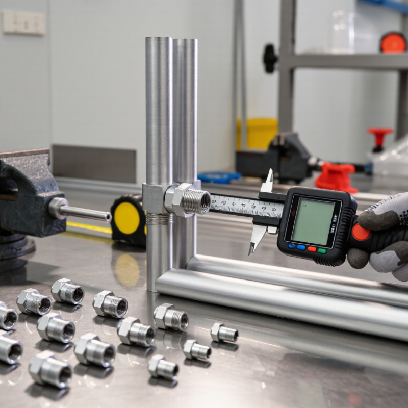
China Top 10 Right Angle Couplers How to Check Torque Resistance

What Right-Angle Couplers Are and Why Torque Resistance Matters

Right-angle couplers connect hoses, pipes, or drive components where a 90-degree turn saves space. Their compact shape is useful near machine frames, pneumatic panels, and rotating assemblies. However, the bend changes how force travels through the joint. A fitting can look secure while twisting internally under vibration.

Torque resistance shows how much rotational load a coupler can withstand before loosening, cracking, or leaking. The U.S. Department of Energy reports that compressed-air leaks can waste 20–30% of compressor output. A poorly secured angled coupler can contribute to that loss, especially around vibrating equipment. This figure is broad, not a guarantee for every factory.

Testing should follow a controlled procedure. Clean the threads, install the coupler with the specified sealing method, and apply torque gradually with a calibrated wrench. Record the first slip point, permanent deformation, and leakage after cycling. ISO 16047 provides a recognized framework for torque and clamp-force testing, while ISO 4414 addresses pneumatic-system safety principles. Compare measured torque with the supplier’s declared working limit, not only the breaking value. Breaking torque is dramatic but not very useful in service.

A practical check uses three samples from the same production lot. Repeat tightening and loosening cycles, then inspect the elbow for whitening, thread damage, or misalignment. Temperature can change results. So can an imperfect wrench. That part is easy to overlook. Data sheets may also omit vibration duration, making comparisons incomplete. Document those gaps before ranking the top ten couplers.

How to Identify and Compare China’s Top 10 Right-Angle Couplers

To identify China’s top 10 right-angle couplers, compare measured performance, not catalog claims. EN 74-1 specifies a 50 N·m tightening torque for comparable testing. Record slip resistance, deformation, and failure mode in each report. A reliable shortlist should include material certificates, dimensional checks, coating thickness, and batch traceability. ISO/IEC 17025-accredited laboratories add stronger evidence.

The details matter. Check whether the coupler grips clean 48.3 mm tubes without sharp edge damage. Measure bolt elongation after repeated tightening cycles. Ten samples per batch can reveal uneven production quality. I would compare average torque resistance, lowest result, and standard deviation. The lowest result matters most. Some suppliers provide attractive test graphs, but omit temperature, loading speed, or sample history. That weakness deserves attention. Field inspections also reveal loose threads, thin galvanizing, and casting pores that laboratory samples may miss. A practical ranking should therefore combine EN 74-1 results, independent inspection records, and at least three production batches. Marketing language is not evidence. Another imperfect point: “top 10” depends on the buyer’s priority, since coastal corrosion, heavy loading, and frequent dismantling require different weighting.

China Top 10 Right Angle Couplers: How to Check Torque Resistance and Compare Right-Angle Couplers

The following table provides an anonymous engineering comparison of common right-angle coupler configurations used in pneumatic, hydraulic, and industrial fluid-control applications. The torque values are practical reference test targets rather than claims for any specific supplier or brand. Always verify the actual product drawing, material certificate, pressure rating, and test report before purchasing.

Rank Reference Coupler Configuration Typical Connection Nominal Size Common Body Material Typical Working Pressure Reference Torque-Resistance Target Recommended Torque Check Acceptance Criteria Best-Suited Application
1 Heavy-duty hydraulic right-angle coupler Female BSPP to male tube thread 1 in Carbon steel with zinc-nickel plating 250 bar 140 Nm minimum reference target Apply torque gradually with a calibrated wrench; inspect after pressure cycling No thread stripping, body cracking, leakage, or permanent angular deformation High-pressure hydraulic manifolds and mobile equipment
2 Stainless-steel instrumentation elbow coupler Male NPT to female tube port 3/4 in 316 stainless steel 200 bar 105 Nm minimum reference target Check dry-thread and lubricated-thread torque separately No galling, thread damage, seal extrusion, or pressure loss Corrosive fluids, chemical processing, and instrumentation lines
3 Compact hydraulic right-angle coupler Male metric thread to female port 1/2 in / 12 mm class Carbon steel or stainless steel 250 bar 75 Nm minimum reference target Use a fixture to prevent the body from rotating during torque application Connection remains leak-free after torque and impulse testing Hydraulic control blocks and compact power units
4 Brass pneumatic push-in angle coupler Push-in tube connection to male thread 3/8 in / 10 mm tube Nickel-plated brass with polymer release ring 10 bar 28 Nm minimum reference target Torque the threaded side first, then perform tube pull-out and leak tests No rotation-induced leakage, tube release, cracking, or damaged collet Factory automation and compressed-air equipment
5 Brass compression right-angle coupler Compression tube fitting to female thread 1/2 in / 12 mm tube Nickel-plated brass 25 bar 42 Nm minimum reference target Measure initial assembly torque and repeatability after disassembly No ferrule slippage, tube deformation beyond specification, or leakage Air, water, lubrication, and low-pressure fluid systems
6 Stainless-steel sanitary angle coupler Tri-clamp or hygienic tube connection 1/2 in to 1 in 304 or 316L stainless steel 10 bar 35 Nm minimum reference target Check clamp torque, gasket compression, and rotational movement No gasket extrusion, clamp distortion, surface cracking, or product-side leakage Food, beverage, pharmaceutical, and clean-process systems
7 Thermoplastic pneumatic angle coupler Push-in tube port to push-in tube port 6 mm tube Polymer body with brass threaded insert 8 bar 15 Nm minimum reference target Apply torque at room temperature and after temperature conditioning No body splitting, insert pull-out, air leakage, or tube release Light-duty pneumatic controls and robotic grippers
8 High-flow hydraulic quick-connect angle coupler Female quick socket to male threaded elbow 3/4 in Hardened carbon steel 315 bar 115 Nm minimum reference target Test both connection torque and repeated connect-disconnect cycles No sleeve seizure, ball damage, seal leakage, or accidental uncoupling Construction machinery and high-flow hydraulic circuits
9 Low-pressure water-service angle coupler Female BSP thread to hose barb 1/2 in Brass or reinforced engineering polymer 16 bar 30 Nm minimum reference target Torque test followed by hydrostatic pressure holding for at least 30 minutes No visible cracks, seepage, hose pull-off, or thread deformation Water treatment, cooling lines, and general utility piping
10 Miniature panel-mount right-angle coupler Bulkhead thread to tube or hose port 1/4 in / 6 mm tube Nickel-plated brass 12 bar 18 Nm minimum reference target Secure the panel nut and test the body against torsional rotation No panel loosening, seal damage, port rotation, or leakage Compact control cabinets and laboratory equipment
How to check torque resistance: Isolate the coupler, clean the threads, identify the thread standard, and mount the part in a fixture that prevents unintended movement. Use a calibrated torque wrench, increase torque gradually, and record the torque at first movement, leakage, visible damage, or permanent deformation. For pressure-service couplers, complete the torque test with hydrostatic or pneumatic leak testing and, where applicable, impulse or pressure-cycle testing.

Technical reference: Torque testing should be aligned with the applicable product specification and relevant standards, such as ISO 7241 for hydraulic quick-action couplings, ISO 4414 for pneumatic systems, ISO 1179 or ISO 9974 for threaded fluid connections, and ISO 6789 for calibration and use of torque tools. Actual allowable torque depends on thread form, lubrication, material, seal design, temperature, and installation method.

Which Design Factors Determine Coupler Torque Resistance

China Top 10 Right Angle Couplers: How to Check Torque Resistance

Right angle coupler torque resistance depends on more than rated load. The joint’s geometry controls how force travels through the connection. A wider body usually spreads stress across a larger contact area. Sharp internal corners can create stress concentration. Smooth transitions are safer in repeated loading.

Material strength matters, but material alone does not decide performance. Wall thickness, heat treatment, thread quality, and surface hardness all affect resistance. The bolt or locking pin must maintain clamping force without slipping. Even a strong coupler can rotate when contact surfaces are oily, uneven, or poorly aligned. Small gaps matter.

In practical inspections, I check the coupler at the intended angle, then apply torque gradually with a calibrated wrench. I record the first movement, permanent deformation, and any surface cracking. A torque test should reflect real tube size, fastener condition, and loading direction. Otherwise, the result may look precise but remain misleading. Temperature and corrosion deserve attention too. Metal behavior changes. I have seen clean calculations fail when assembly tolerance was ignored. That weakness is worth admitting. A reliable design combines sufficient section thickness, secure locking features, accurate fit, and verified test data.

How to Prepare a Safe Right-Angle Coupler Torque Test

A safe right-angle coupler torque test begins with controlled preparation, not the wrench. Inspect the body, bolt, nut, threads, and contact surfaces for cracks, distortion, rust, or embedded debris. Record tube diameter, coupler batch, material condition, and ambient temperature. EN 74-1:2005+A1:2008 evaluates couplers through slip resistance, tensile strength, and stiffness tests. It does not create one universal torque value for every design.

Secure the coupler on a rigid test frame with correctly sized tubes. Align the joint carefully; even a small angular error can change the load path. Use a calibrated torque wrench verified under ISO 6789-2:2017 procedures, and document its uncertainty. Apply torque gradually, with a steady motion. Do not shock-load the bolt. Mark the starting position, then record torque, rotation, visible slip, thread damage, and permanent deformation. Repeat the test on several samples. One result is not enough.

Stop immediately if the tube slips, the bolt bends, or cracking appears. A torque reading alone can mislead. Friction, lubrication, thread wear, and surface coating may alter clamp force substantially. ASTM F606/F606M-24 also demonstrates why fastener testing needs controlled procedures and repeatable measurements. I would question any report that lists only a maximum torque. The fixture may be the weak point. Recheck calibration, alignment, and operator technique before accepting the result. Safety barriers and remote observation add practical protection during failure.

China Top 10 Right-Angle Couplers: How to Check Torque Resistance

Safe Right-Angle Coupler Torque Test Reference

How to use this reference: The chart converts applied torque into the equivalent force required at a 100 mm effective lever arm using the formula Force = Torque ÷ Lever Length. For example, 20 N·m requires 200 N at 100 mm. During testing, secure the coupler and mating components, apply torque gradually, monitor deformation or slippage, and never exceed the coupler’s specified torque rating. The actual acceptance limit must come from the applicable product specification or test standard.

How to Measure, Record, and Evaluate Torque Resistance Results

China Top 10 Right Angle Couplers: How to Check Torque Resistance

Torque resistance testing for right angle couplers should begin with a clean, stable fixture. Secure the coupler without crushing its housing. Use a calibrated torque transducer or torque wrench with a suitable range. Apply torque gradually in the specified direction. Stop at each test point and check for slipping, cracking, thread damage, or permanent movement. Record the applied torque, rotation angle, temperature, test speed, and fixture identification.

Consistency matters. Test several samples from the same production lot, not only one convenient piece. A useful record includes the sample code, operator, equipment calibration date, peak torque, residual deformation, and failure description. Photographs can clarify marks that numbers cannot. Small details matter. A clean result may still mislead if the fixture flexes or the contact surfaces are oily.

Tips: Mark the starting position with a fine line. Zero the instrument before every series. Increase torque in equal steps, such as 5 or 10 N·m, according to the approved procedure. Compare results with the drawing or internal specification, rather than relying on a general industry assumption. Evaluate the average, minimum value, range, and failure mode. If one sample differs sharply, repeat the test and inspect the setup before rejecting the entire lot. The measurement process itself may be the weak point.

FAQS

What is a right-angle coupler?

It connects hoses, pipes, or drive components through a 90-degree turn. Its compact shape saves space near frames and pneumatic panels.

Why does torque resistance matter?

Torque resistance shows how much rotational load a coupler can withstand. Excessive torque may cause loosening, cracking, or leakage. Vibration can twist the joint internally. Looks secure, sometimes isn’t.

How should torque testing begin?

Clean the threads and contact surfaces. Install the approved sealing method. Secure the coupler without crushing its housing. Use a calibrated wrench or torque transducer.

What should a torque test record?

Record applied torque, rotation angle, temperature, test speed, and fixture identification. Include the sample code and calibration date. Photographs can show damage that numbers miss.

How many samples should be tested?

Test at least three samples from one production lot. Repeat tightening and loosening cycles. Inspect for whitening, thread damage, leakage, or misalignment. One sample may mislead you.

How should torque results be evaluated?

Compare measured torque with the declared working limit. Do not rely only on breaking torque. Review the average, minimum, range, and failure mode. Breaking values look impressive but may not reflect service conditions.

What can make test results unreliable?

Temperature can change the result. An imperfect wrench can also distort measurements. Fixture flex, oily surfaces, and uneven contact create additional errors. This part is easy to overlook.

How can testing become more consistent?

Mark the starting position with a fine line. Zero the instrument before each series. Increase torque in equal steps, such as 5 or 10 N·m. Follow the approved procedure. Small details matter.

What should happen when one sample differs sharply?

Repeat the test and inspect the fixture before rejecting the entire lot. Check calibration, surface cleanliness, and mounting pressure. The measurement process itself may be the weak point. That possibility deserves reflection.

Conclusion

This guide explains what right-angle couplers are and why torque resistance is essential for connection safety, structural stability, and long-term performance. It presents a practical method for comparing China’s top 10 right-angle couplers through key specifications such as material strength, coupling geometry, locking structure, surface treatment, and manufacturing consistency. Instead of relying only on listed ratings, readers will learn how to assess whether a coupler can withstand twisting forces under realistic working conditions.

The article also describes how to prepare a safe and repeatable torque test, including equipment selection, sample inspection, fixture alignment, and gradual load application. It explains how to check the torque resistance of right angle couplers, record torque values, identify deformation or slippage, and evaluate results against the intended application requirements. By using consistent testing procedures and clear documentation, buyers and engineers can make more reliable comparisons and select couplers with suitable resistance, durability, and safety margins.

Sophia

Sophia

Sophia is a dedicated marketing professional with an exceptional depth of knowledge about her company's products and services. With a keen understanding of market trends and customer needs, she crafts insightful blog posts that not only inform but also engage readers, enriching the company’s online......