ABP Scaffolding
A sleeve coupler looks simple, but its reliability depends on controlled installation. Threads, shoulders, seals, and connected components must share the applied load correctly. When installation feels loose, some technicians instinctively add more force. That decision can create hidden damage before the joint ever enters service. What happens when you overtighten a sleeve coupler? Excessive torque can stretch the threads, deform the sleeve, crush a seal, or create stress concentrations near the coupling ends. The joint may feel extremely secure. It may already be weakened.
In practical applications, overtightening can also reduce alignment accuracy. A distorted coupler may place bending forces on shafts, pipes, cables, or connected fittings. Those forces can produce vibration, leakage, fatigue cracks, or premature separation. The visible damage is not always dramatic. Sometimes, only a flattened thread crest or a small crack reveals the problem. That is the trap. A proper inspection should include thread condition, surface damage, alignment, and evidence of galling. Manufacturer torque values remain the most reliable reference because coupler materials and designs vary widely.
A calibrated torque wrench helps prevent guesswork. Clean threads matter, too, because dirt and corrosion can change friction and produce misleading torque readings. Do not assume maximum tightness means maximum strength. That assumption deserves reconsideration. In some cases, replacing a damaged coupler is safer than attempting another adjustment. Installation records, product specifications, and inspection findings also improve traceability. This article examines why overtightening causes failure, how the damage develops, and which practical checks can help technicians avoid repeating an easy but costly mistake.
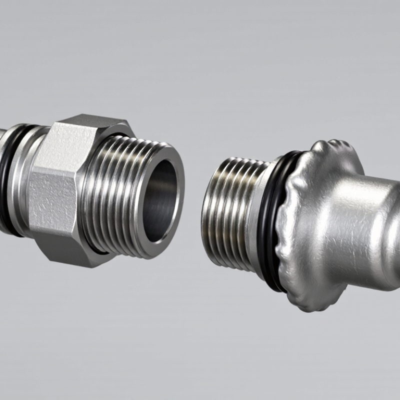
A sleeve coupler joins two mechanical members and keeps their loads aligned. Its main job is controlled load transfer, not simply clamping parts together. The sleeve supports the connection around a joint, while threads, bolts, or pins create the required preload. That preload helps prevent separation, slipping, and vibration under service loads. Alignment matters too. A slightly tilted sleeve can concentrate stress along one edge.
Overtightening changes this balance. Excessive torque can stretch fasteners beyond their elastic range or crush the sleeve locally. Threads may deform, and the bore can become oval. Cracks may begin near a shoulder, thread root, or sharp corner. These defects are often difficult to see. Look for fretting dust, polished contact marks, displaced metal, or a joint that feels unusually stiff. A small mistake matters.
The correct installation uses clean contact surfaces, accurate alignment, and a calibrated torque tool. Torque should follow the applicable engineering specification, not personal judgment. “Tighter feels safer” is a common assumption, but it is incomplete. In practice, even experienced technicians can miss surface damage or misread a torque value. A careful inspection after loading can reveal movement, uneven contact, or fresh marks around the sleeve. Those details deserve attention before the connection returns to service.
Why Does Overtightening a Sleeve Coupler Cause Failure?
A sleeve coupler transfers load through contact pressure, friction, and thread engagement. Tightening force increases clamping stress around the sleeve. Past the design range, that stress can exceed the material’s elastic limit. The sleeve may ovalize, split, or permanently deform. Threads can also gall or strip. In rotating assemblies, this damage creates uneven contact. Small misalignment then becomes vibration, heat, and fatigue cracking.
The NASA Fastener Design Manual, NASA-RP-1228, reports that torque-based preload can vary by roughly ±25% because of friction. This matters. The same wrench setting may produce very different coupler stress. Thread friction, surface finish, lubrication, and tool angle all change the result. ASME PCC-1 also emphasizes controlled tightening procedures and calibrated tools for bolted joints. In field inspections, a crushed sleeve edge is often a warning sign, not proof of stronger assembly. I have seen operators chase looseness with more torque, although the real problem was poor fit or contamination. That assumption deserves review.
Tips: Use the manufacturer’s specified torque and tightening sequence. Confirm thread condition, sleeve alignment, and lubrication requirements. Mark the fastener after tightening. Check for distortion with a straightedge or bore gauge. For critical joints, measure preload directly when practical. Torque is only an estimate of force. Surface conditions can quietly change everything.
Why Does Overtightening a Sleeve Coupler Cause Failure?
Excessive torque can deform a sleeve coupler before the joint appears secure. The threads may flatten, stretch, or gall under the tightening load. This changes the contact pattern and creates local stress peaks. Cracks often begin near thread roots, shoulders, or sharp geometric transitions. Small surface marks can become serious fatigue flaws.
NASA-RP-1228, the Fastener Design Manual, reports that only about 10% of applied torque produces useful bolt stretch. Roughly 50% is lost through thread friction, while another 40% is lost beneath the bearing surface. This explains why a small torque increase can produce a large and uneven load change. ISO 16047 also emphasizes that friction strongly affects torque-to-clamp-force results. Torque alone is not a reliable measure of joint security.
In field inspections, operators sometimes tighten until the sleeve “feels solid.” That assumption is too simple. A hardened tool, dirty thread, or incorrect lubricant can raise contact stress quickly. The coupler may look acceptable but contain microscopic cracks. I have seen torque records treated as proof of quality, even when thread condition was never checked. That is a weak control. Use the specified torque range, inspect deformation, and verify the joint with the applicable dimensional or proof-load procedure. Stop early. Damage may already have started.
| Relative Torque Condition | Clamp Load Trend | Mechanical Response of the Sleeve | Typical Stress or Deformation | Likely Failure Mode | Inspection Indicators |
|---|---|---|---|---|---|
| Below the specified torque | Preload is lower than the design target. Joint resistance depends strongly on friction, alignment, and service vibration. | The sleeve may not fully conform to the mating surfaces, leaving insufficient sealing or mechanical engagement. | Low contact pressure; possible micro-movement at the joint interface. | Leakage, loosening, fretting, or pull-out under axial load. | Visible seepage, witness marks, joint movement, or torque loss during rechecking. |
| At the specified torque | Nominal preload is achieved when the correct fastener condition, lubrication state, thread engagement, and assembly method are used. | Elastic deformation provides contact without permanently changing the sleeve geometry. | Stress remains below the material’s local yield limit in a correctly designed assembly. | Normal service performance when installation and component tolerances are correct. | Uniform seating, no sharp circumferential marks, and stable torque after assembly. |
| Approximately 10–20% above target torque | Clamp load tends to increase by a similar proportion if the friction coefficient remains constant; actual preload can vary substantially because friction often consumes most of the applied torque. | Local yielding may begin at thread roots, conical seats, thin sleeve walls, or contact edges, depending on geometry and material. | Permanent ovality, local indentation, or increased contact-band width may occur. | Reduced sealing margin, distorted threads, and loss of preload after thermal or pressure cycling. | Flattened contact areas, thread galling, displaced material, or a sleeve that no longer rotates or seats normally. |
| Approximately 20–50% above target torque | Excessive preload can push the joint beyond its intended load capacity, especially where the sleeve wall is thin or the thread diameter is small. | Plastic deformation becomes more likely; the sleeve can be driven deeper into the mating component than intended. | Localized stress concentrations develop at sharp shoulders, thread run-outs, grooves, and changes in wall thickness. | Crushing, permanent leakage, thread stripping, or cracking at stress-concentration points. | Visible bulging, circumferential cracks, torn threads, unusual assembly resistance, or a measurable loss of roundness. |
| More than 50% above target torque | Additional torque may produce little useful clamp load because parts have yielded, friction has increased, or threads are damaged. | The sleeve may split, buckle, seize, or become permanently wedged between mating parts. | Local stress can exceed the yield strength and approach the material’s fracture resistance, particularly at notches or cold-worked regions. | Sudden cracking, brittle fracture, stripped threads, or complete loss of pressure containment. | Audible cracking, abrupt torque drop or spike, visible fracture lines, metal debris, or inability to disassemble normally. |
| Repeated over-torque and reuse | Preload becomes unpredictable because the sleeve and threads may already contain residual plastic strain or surface damage. | Repeated assembly can enlarge contact marks and propagate small cracks through cyclic loading. | Residual tensile stress remains around deformed regions; vibration and pressure cycling can accelerate crack growth. | Fatigue cracking, intermittent leakage, and failure during subsequent service cycles. | Crack growth from existing marks, recurring leaks at the same location, or inconsistent torque-to-seating behavior. |
| High-friction or contaminated threads | A larger percentage of the applied torque is consumed by thread and bearing friction, so the resulting clamp load may be lower or less predictable than expected. | Uneven friction can cause jerky tightening, localized contact, and non-uniform sleeve compression. | As a general relationship, T ≈ K × F × d, where T is torque, F is preload, d is nominal diameter, and K is the friction factor. | Under-tightening, over-tightening after repeated attempts, galling, or uneven deformation. | Stick-slip motion, inconsistent torque readings, damaged threads, dirt, corrosion, or lubricant applied contrary to the procedure. |
| Engineering note: Torque values are design-specific and must be taken from the applicable assembly specification. The same torque does not produce the same clamp load when thread diameter, pitch, material, surface finish, lubrication, temperature, or friction condition changes. For reference, minimum yield strengths commonly specified for annealed 316 stainless steel plate and 6061-T6 aluminum alloy are approximately 205 MPa and 240 MPa respectively; the actual sleeve material, heat treatment, wall thickness, and geometry determine the allowable stress. Any sleeve showing permanent deformation, cracking, galling, or thread damage should be replaced rather than reused. | |||||
Why Does Overtightening a Sleeve Coupler Cause Failure?
How Overtightening Leads to Leakage and Joint Failure
A sleeve coupler depends on controlled compression, not maximum force. Overtightening can crush the sleeve, distort the pipe, and damage the sealing surface. The seal may appear secure during assembly. Pressure and temperature changes can expose the weakness later. Small cracks, flattened sealing lips, or extrusion paths may then allow fluid to escape.
The uncomfortable part is simple: tighter feels safer, but feel is not measurement. NASA’s Fastener Design Manual, NASA Reference Publication 1228, explains that friction consumes most tightening torque. Only about 10% often becomes useful bolt preload. Dirty threads, surface coatings, and tool angle can change that result. A technician may apply the specified torque yet create excessive compression. This is where practice becomes imperfect.
ASME B31.3 emphasizes controlled assembly and inspection for process piping joints. The NACE IMPACT study estimated global corrosion costs at 2.5 trillion dollars in 2013, equal to about 3.4% of global gross domestic product. That figure is not caused by couplers alone, but leakage control remains a practical reliability concern. Inspectors should check the sleeve gap, pipe roundness, witness marks, and signs of seal extrusion. A calibrated torque tool helps. So does a documented assembly record. Pressure testing should follow the applicable engineering procedure, because a dry joint can hide damage. Reusing a deformed sleeve is also a poor gamble. Sometimes, the failed part looked perfect at installation.
Excessive tightening can deform the sleeve, reduce sealing conformity, and increase joint stress. The chart shows the representative relationship between tightening torque and leakage or joint-failure incidents.
Torque is expressed as a percentage of the recommended installation torque. Incident rates are shown per 100 tested joints and represent a typical engineering trend: risk rises sharply once the recommended torque is exceeded.
Why Does Overtightening a Sleeve Coupler Cause Failure?
The correct tightening torque begins with the required clamp load, not the maximum wrench setting. For a threaded sleeve coupler, use T = K × F × d, where T is torque, K is the friction factor, F is preload, and d is nominal diameter. Thread condition changes K significantly. Dry, plated, lubricated, or contaminated threads can produce different preload from the same torque. NASA’s Fastener Design Manual, NASA-RP-1228, reports that torque control may create preload variation of about ±25%. That margin is easy to ignore.
Overtightening can stretch the coupler beyond its elastic range. Threads may deform, the sleeve may crack, and connected parts can lose alignment. In thin-wall designs, local crushing may appear before visible damage. ASME PCC-1 emphasizes controlled bolt-up, calibrated tools, clean contact surfaces, and documented procedures for pressure-boundary joints. Experience matters here. A torque chart is only a starting point. The actual assembly needs verification.
Tips: Confirm the coupler material, thread size, lubricant, and target preload. Use a calibrated torque wrench. Tighten gradually in stages, when the joint design allows it. Mark the final position. If torque rises suddenly before seating, stop and inspect. A simple trial assembly can reveal galling or thread damage. It may seem slower, but replacing a failed sleeve is slower still. Recheck the specification; assumptions often survive longer than the hardware.
It joins two mechanical members and transfers loads in a controlled way. It also helps maintain alignment. The sleeve supports the joint, while fasteners create preload. That preload limits separation, slipping, and vibration.
Excessive torque can stretch fasteners beyond their elastic range. It may also crush the sleeve or deform its threads. The bore can become oval. Small cracks may start near shoulders, thread roots, or sharp corners.
Too much compression can crush the sleeve and distort the connected pipe. It may damage sealing surfaces or flatten sealing lips. A seal can look sound during assembly. Pressure and temperature changes may reveal leakage later.
No. Tightening by feel is unreliable. Friction can consume much of the applied torque. Dirty threads, coatings, and tool angle can change the actual preload. A specified torque value still needs careful application.
Clean the contact surfaces before assembly. Align the members accurately. Use a calibrated torque tool. Follow the applicable engineering specification, not personal judgment. A small alignment error can load one sleeve edge heavily.
Look for fretting dust, polished contact marks, and displaced metal. Check for uneven contact around the sleeve. A joint that feels unusually stiff may need inspection. Fresh marks can show movement after loading. Some damage remains hidden.
Inspect the sleeve gap, pipe roundness, witness marks, and seal condition. Look for extrusion paths or new deformation. Confirm that the joint has not shifted. Pressure testing should follow the applicable engineering procedure. A dry joint can hide damage.
Reusing a deformed sleeve is a poor gamble. Replace it when crushing, ovality, cracking, or seal damage appears. The part may have looked perfect during installation. That is the uncomfortable part. Inspection records can help prevent the same mistake.
A sleeve coupler joins two mechanical components by distributing clamping force across their connected surfaces, helping maintain alignment, stability, and load transfer. Proper tightening creates enough contact pressure to prevent movement without damaging the coupler or the parts it connects. Understanding what happens when you overtighten a sleeve coupler is essential: excessive torque increases internal stress beyond the material’s design limits, which can distort the sleeve, damage threads, and create cracks or permanent deformation.
Overtightening may also reduce the joint’s ability to seal correctly. Deformed surfaces or damaged sealing elements can produce gaps, allowing fluid or air to leak and eventually causing loosening, misalignment, vibration, or complete joint failure. To avoid these problems, select a coupler suited to the application, follow the manufacturer’s torque specifications when available, and use a calibrated torque tool. Consider material strength, connection size, operating pressure, temperature, and lubrication, since each factor can affect the correct tightening value.